The Goggles
WAIVER AND LIMITATION OF LIABILITYThis product is intended for recreational use only. The designer and manufacturer are not responsible for any misuse of this product, nor for any unintended consequences. This product contains a repetitive light flickering program which may induce headaches, vertigo, nausea, or seizures in some individuals. A history of stroke, traumatic brain injury, and epilepsy, and also some medications can increase your risk of these effects. Purchaser and user assumes any and all risk of use of this product. Designer and manufacturer are not liable for any physical, medical or psychological consequences which may result from the use of this product.
Whats going on here?
Many people see geometric patterns when looking at flickering lights. The patterns depend on the frequency, color, and intensity of the flickering. People report seeing similar shapes, which care common in visual hallucinations and are called “form constants”. Flicker hallucinations are best induced using a Ganzfeld (German for “entire field”), a totally immersive and uniform visual stimulation. Although the Visor is not a complete Ganzfeld, it is immersive enough to demonstrate the flicker hallucination effect. The Visor has been carefully programmed and tuned to display a wide range of colorful patterns, allowing you to experience how the geometric hallucinations change with frequency and color.
How does it work?
Basically, the flickering light confuses the eye and the brain, causing them to misinterpret what they’re seeing. One hypothesis is that the flickering interacts with natural ongoing oscillations in visual cortex, exciting a specific frequency of brain waves. This increases the activity in visual cortex. Activity can increase enough to overload the circuitry the brain uses for interpreting what it sees, causing you to see things that aren’t really there. One model of visual hallucinations has shown that flickering lights can cause visual cortex to behave like a ‘reaction diffusion system’, which is a type of system that spontaneously forms patterns. The most famous examples of biological reaction-diffusion systems are the patterns in animal fur, like leopard spots and zebra stripes. For a more detailed explanation, as well as some modeling and simulation of the phenomena, check out this publication. If all of that seemed too serious, rest assured that the Visor also makes and excellent costume addition for partying, or simply creating a spectacle.
Get Started!
In this parts bundle should be :
1 translucent acrylic visor outer panel
1 translucent acrylic visor middle panel
1 translucent acrylic visor inner panel
1 2xAAA battery pack
1 Visor controller printed circuit board
1 pre-programmed AtTiny24 microcontroller
1 14 pin DIP chip socket
1 8-pin right angle male header
2 4-pin female jumper cables
2 RGB LEDs
1 Blue LED
1 Ultraviolet LED
2 68 ohm resistors
1 10Kohm resistor
4 tactile switches
1 toggle power switch
1 5" length of 22 gauge wire
Along with your parts bundle, you should have received :
1 pair of welding goggles
2 AAA batteries
You will also need these tools :
A hot glue gun and hot glue sticks
A soldering iron
Solder
Super Glue (optional)
The assembly has been broken down into six stages for your convenience. Follow the instructions in each phase in succession, starting from phase I. Click on the links below to navigate to the instructions for each phase.
Project Stages:
Credits
motivation and logistics
Deren Guler
artwork, visor concept
Austin Redwood
software consulting, laser cutting
Keegan McAllester
kit design and creation
Michael Rule
Original Inspiration Michael Rule, Matthew Stoffregen, Bard Ermentrout
The assembly has been broken down into six stages for your convenience. Follow the instructions in each phase in succession, starting from phase I. Click on the links below to navigate to the instructions for each phase.
Project Stages:
- The Visor
- Phase I : The Board
- Phase II : The Optics
- Phase III : Holes
- Phase IV : Power
- Phase V : Light
- Phase VI : Finish and Play
- Usage Notes
Credits
Deren Guler
artwork, visor concept
Austin Redwood
software consulting, laser cutting
Keegan McAllester
kit design and creation
Michael Rule
Phase I : The Board
Prepare you soldering station and heat up your soldering iron.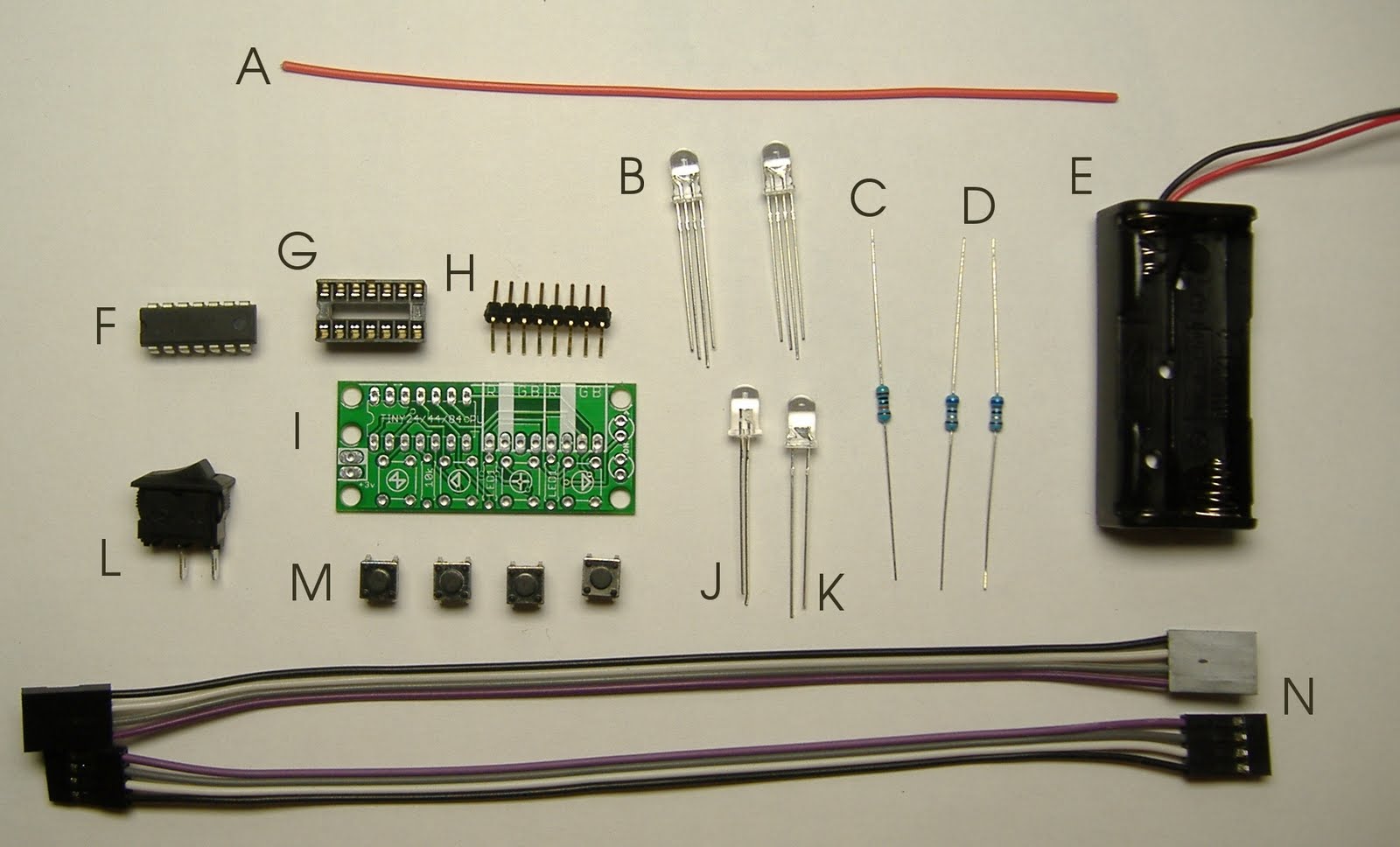
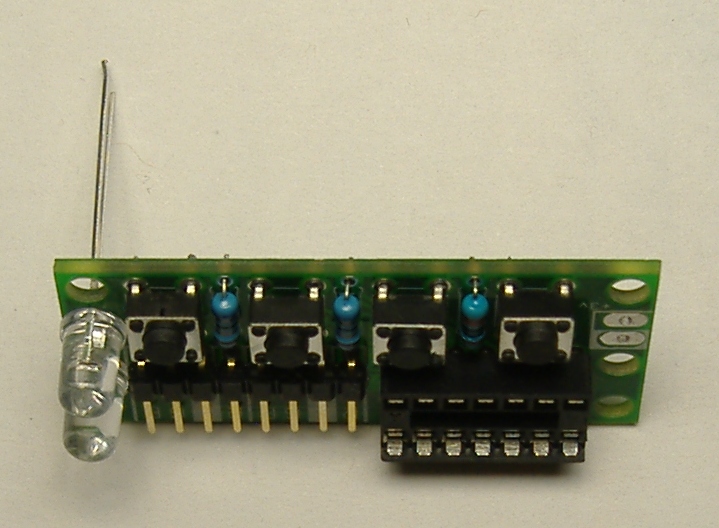
Make sure you have all parts pictured here. Listed from top to bottom, left to right, in the picture shown :
A   1 5" length of 22 gauge wire
B   2 RGB LEDs
D   2 68Ω resistors ( blue grey black gold brown )
C   1 10KΩ or 100KΩ resistor ( brown black black orange brown )
E   1 2xAAA battery pack
F   1 pre-programmed AtTiny24 microcontroller
G   1 14 pin DIP chip socket
H   1 8-pin right angle male header
I   1 Visor controller printed circuit board
J   1 Blue LED
K   1 Ultraviolet LED
L   1 toggle power switch
M   4 tactile switches
N   2 4-pin female jumper cables

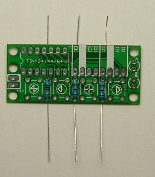
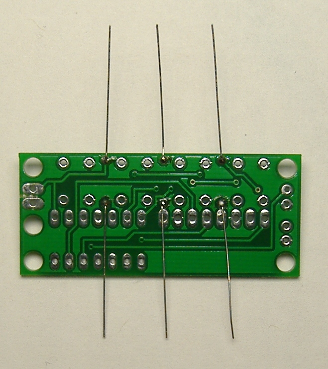
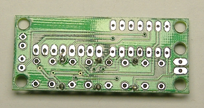
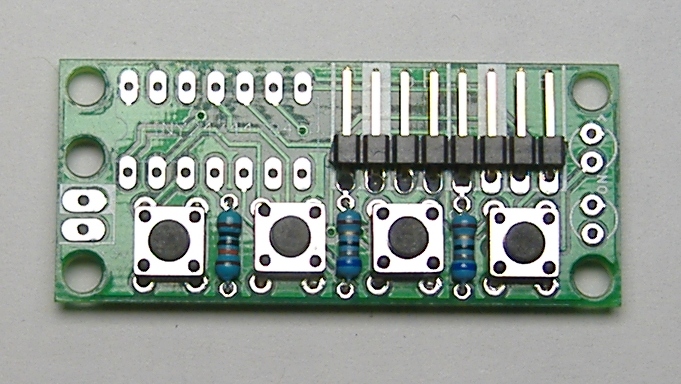
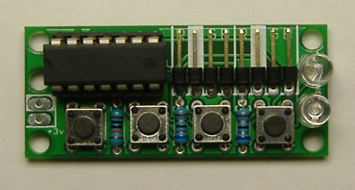
Locate the three resistors and bend the leads at a right angle close to the body, as shown. The LED resistors are 68Ω ( blue grey black gold brown ). The reset pull-up resistor is 100KΩ ( brown black black orange brown ). Insert the resistors into the board. The two 68 ohm resistors go on the right, at shown, in the slots marked "LED". The reset pull-up resistor goes in the slot on the left marked "10k". Optionally bend the leads outward to hold the resistors in place while you solder them. Solder the resistors, and trim the excess leads with a wire cutter.

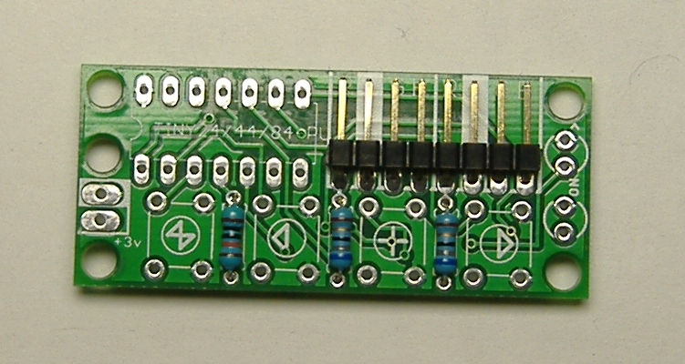
Place the 8-pin right-angle connector for the RGB LED cables as shown. Note that the plastic part of the header should surround the part of the header that is parallel to the board. Turn the board over and solder the 8-pin right angle connector. A common trick to get the connector flush against the board is to solder one pin. Then, melt that solder joint while pressing the connector flush against the board, and let it cool again. Solder the remaining pins.


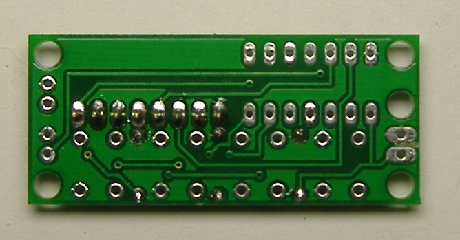
Place the tactile switches on the board as shown. Note that, if the tactile switches are places sideways, the board will not function. Turn the board over and solder the tactile switches in place.

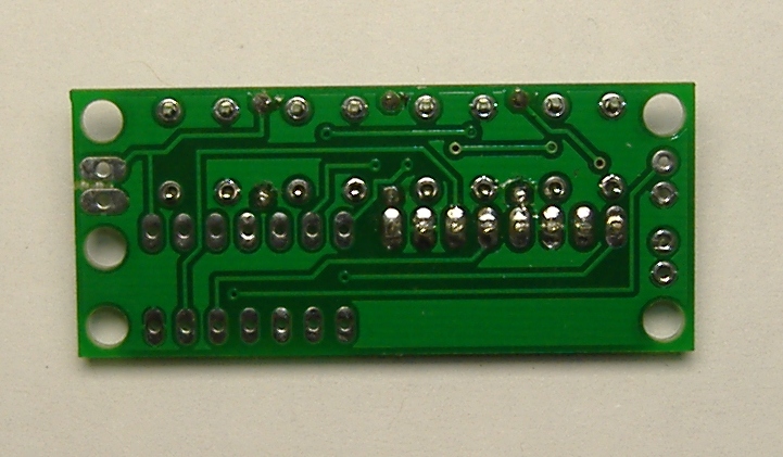

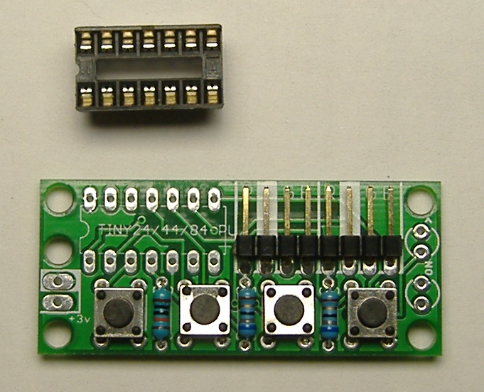
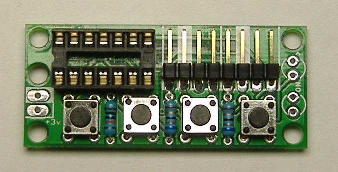
Solder the chip socket. Note that there is a U shaped notch in one side of the socket. This indicates the orientation of the socket. Place the socket so that this notch is on the left as shown. One trick to get the socket flush against the board is to solder one corner pin, then melt that solder joint, position the socket so that it is flush, and let the joint cool. Then, do the same thing on the opposite corner. The socket is now held in place, leaving you free to solder the remaining pins.
Solder the indicator LEDs. It is important to insert these LEDs in the correct direction, otherwise they will not light. The LED has two leads. One leads is the "ground" LED. This lead will be shorter. IF you look closely at the plastic part of the LED, the base on one side will be flat. This also indicates the side of the LED with ground lead. In our case, thr ground lead should be at the top, as pictured here. Solder both indicator LEDs. One will be purple and one will be blue, but it does not matter which one goes where.


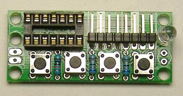

Trim any extra leads sticking out of the bottom of the board with wire snips.

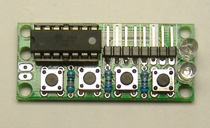
Locate the AtTiny24 microcontroller chip. Note that one end of the chip has a U shaped notch, just like the socket. This indicates the orientation of the chip, and it is important to insert the chip in the correct orientation, otherwise the board will not work. The notch should be on the left as pictured. Carefully insert the microcontroller into its socket.

This completes the board assembly phase of the project.
Project Stages:
- The Visor
- Phase I : The Board
- Phase II : The Optics
- Phase III : Holes
- Phase IV : Power
- Phase V : Light
- Phase VI : Finish and Play
- Usage Notes
Phase II : The Optics
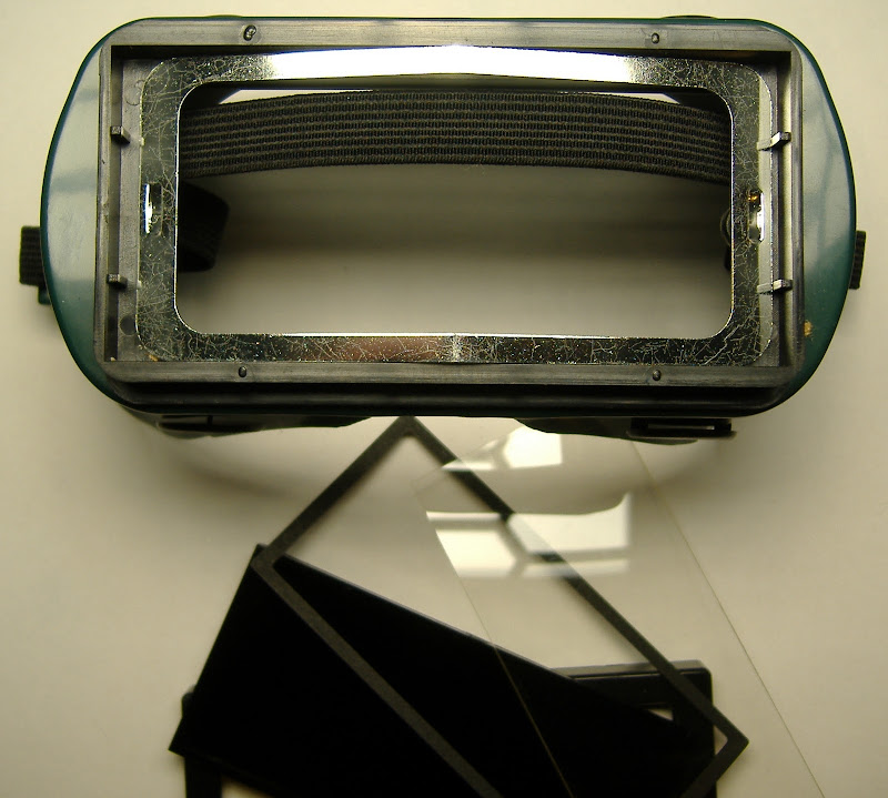
We are going to modify a pair of welding goggles to make the Visor.
Slide the outer bracket of the goggles, and remove the tinted and clear plastic plates from the welding goggles. Leave the metal bracket.


Locate the translucent white plastic pieces that came with your kit. There should be three of them. One has a small notch cut into the side. This notch is for the RGB-LED wires, and this pieces will go on inside later. Another has a picture of some LEDs etched into the surface. This is the inner panel, and you will attach the LEDs to its surface. The third has a decorative pattern etched into its surface. This panel goes on the outside.
(The etching is not shown in these instructions, because the photos were taken before this was added to the design.)
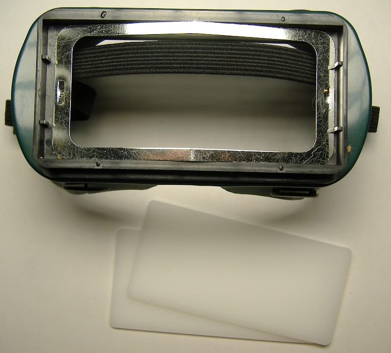
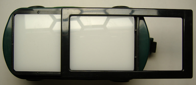
Stack the decorative panel on top of the inner panel, so that the LED markings are on the bottom surface, and the decorative markings are on the top. Place these pieces into the goggles where the tinted plastic used to be, and slide the bracket closed again. You should see a decorative pattern on the front of the goggles, and markings for positioning the LEDs on the inside of the goggles.

This completes phase II.

Project Stages:
- The Visor
- Phase I : The Board
- Phase II : The Optics
- Phase III : Holes
- Phase IV : Power
- Phase V : Light
- Phase VI : Finish and Play
- Usage Notes
Phase III: Holes
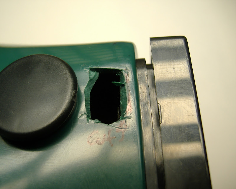
Get out your x-acto or hobby knife, and do be careful. We are going to make some cuts into the goggles to pass wires through, and also a place to hold the power switch.
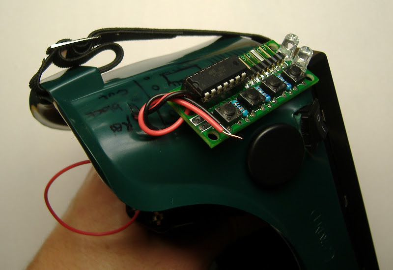
Observe the markings in this picture. You can attach the electronics in many creative ways, but this is the way I assembled it. Wherever you decide to place the board, cut a small slit for the power wires near the power connector on the board ( the one remaining un-soldered place on the board ). Also, at some distance away from the 8 pin right angle connector for the LEDs, cut a 3/4" 1.5cm long slit for the LED cables.


The power switch is best placed at the top, as pictured below. Draw a rectangular outline slightly smaller than the top of the power switch, and remove it with a x-acto knife. Try to insert the power switch into the hole for a test, and adjust the size of the hold if necessary.


This completes phase III.

Project Stages:
- The Visor
- Phase I : The Board
- Phase II : The Optics
- Phase III : Holes
- Phase IV : Power
- Phase V : Light
- Phase VI : Finish and Play
- Usage Notes
Phase IV : Power
The power supply needs to be soldered to the circuit board in place, in order to have the batteries on the inside of the goggles, and the circuit board on the outside. This is a bit tricky.
Solder the red (+) wire from the battery pack onto one lead of the power switch, and the red jumper wire onto the other. Insert the power switch into the goggles as shown below.

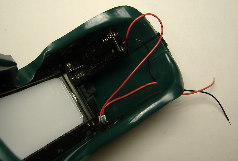
Next we are going to solder the power wires into the board. Wires that are soldered directly onto the board can break loose. One way to make the connection stronger is to tie the wires to the board before you solder them. We've provided a hole next to the power connection for this purpose. If you find this too challenging, it is not strictly necessary, as there shouldn't be too much strain on the power wires in typical use.


Solder the power cables as shown below, making sure that the red (+) wire goes into the hole labeled "+3v", and the black (-) wire in the other pad with the filled in white marking. Optionally, use the knot trick as shown to reduce strain on this solder connection.


If you have two AAA batteries, you can put them in the battery holder and turn on the power switch to see if the board works. The power-on LED should light up if everything is working correctly. If this does not happen, you will need to troubleshoot the board. Check that the indicator LEDs are inserted in the correct orientation, and that the red (+) wire from the batter is indeed connection to the +3v marked pad on the board. Look for loose or broken solder connections, and make sure the batteries you are using to test are charged.

This completes phase IV.
Project Stages:
- The Visor
- Phase I : The Board
- Phase II : The Optics
- Phase III : Holes
- Phase IV : Power
- Phase V : Light
- Phase VI : Finish and Play
- Usage Notes
Phase V: Light
Next, we are going to wire up and place the red, green, and blue (RGB) LEDs which generate the flickering light pattern.
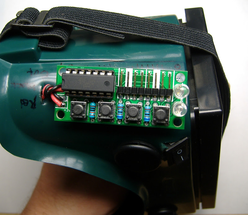
Attach the jumper cables for the LEDs to the 8-pin connection as shown above. Their orientation does not matter, though for consistency you should orient them the same way. Pay attention to the markings underneath the header, which have the labels "R", "G", and "B" for "red", "green", and "blue" color channels, as well as a filled-in white region indicating the ground (-) pin for the LEDs. You will want to remember which color wire corresponds to the ground pins for later.

Thread the jumper cables one after another through the slit you prepared earlier.

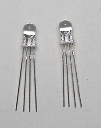
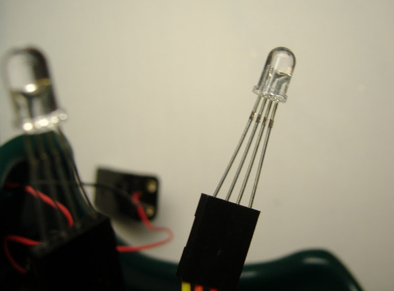
The inside of the goggles should now look something like this. Next we're going to insert the colored LEDs into the viewing area. These are the LEDs with four leads. In order, these leads are R(ground)GB. Examine the RGB LEDs closely. Like the indicator LEDs, one side of the plastic housing is flat on the bottom. As before, this indicates the side of the LED with the ground lead. You will want to insert the LEDs into the jumper cables such that the ground lead of the LED matches up with whicever color wire is the ground wire, which was noted in the previous step. You may optionally want to trim the LED leads to all the same length to make inserting the LEDs into the jumpers easier, or to adjust the spacing between the LEDs.


Turn on the goggles and test that the RGB LEDs are working. The first pattern on the goggles is a white flickering stimulus. If either LED does not appear white, you may have some missed connections. Try adjuting the LEDs and trimming the leads slightly if you are not getting a connection. If that fails, check that the jumpers are placed securely on the board header, and that the board header is soldered completely. If all color channels of both LEDs are working, turn of the goggles and proceed.

Now, glue the LEDs in place as indicated by the etched markings, and as demonstrated here. Either super glue or hot glue will work. I found the gluing the ends of the jumpers together with a bit of super glue first made positioning easier. You may want to tack down the LED wires as shown to keep them in place.
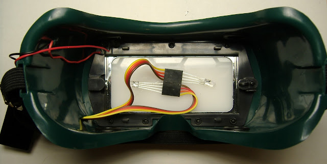
Insert the inner translucent plastic piece, feeding the wires out through the notch provided.


Your goggles are nearly complete! The only thing left to do is to tie down some loose ends and hold everything in place.

This completes phase V.
Project Stages:
- The Visor
- Phase I : The Board
- Phase II : The Optics
- Phase III : Holes
- Phase IV : Power
- Phase V : Light
- Phase VI : Finish and Play
- Usage Notes
Phase VI: Finish and Play
All that's left is to tie down the the loose pieces with a bit of hot glue.
You can temporarily detach the LED cables to glue the circuit board to the visor. Some people have also had success zip tying the board to the visor (not shown). To do this, poke holes in the visor beneath the corner holes in the circuit board, and thread your fastener through there to tie down the board.

Glue the battery pack in position as shown. You may secure the battery pack wherever is comfortable, as there is nothing unique about this position.

Organize the wires on the inside and move them out of the field of view. Tack everything down with some glue to hold it in place.

That's it, you're done! Power on.
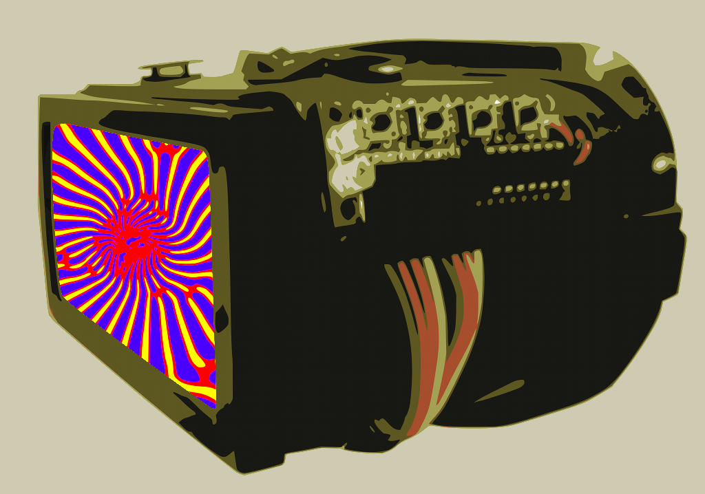
Experiment !
Try drawing what you see, and comparing this experience with a friend. Start to experiment. Do different people the same things? Does the experience seem to change when you are more alert, or more tired? Open or closed eyes? Do you see the same patterns on the same presets across different days? If all of that gets too serious, the Visor also makes and excellent costume addition for partying, or simply creating a spectacle.
Try drawing what you see, and comparing this experience with a friend. Start to experiment. Do different people the same things? Does the experience seem to change when you are more alert, or more tired? Open or closed eyes? Do you see the same patterns on the same presets across different days? If all of that gets too serious, the Visor also makes and excellent costume addition for partying, or simply creating a spectacle.
Project Stages:
- The Visor
- Phase I : The Board
- Phase II : The Optics
- Phase III : Holes
- Phase IV : Power
- Phase V : Light
- Phase VI : Finish and Play
- Usage Notes
Usage Notes
Here is a cartoon of the board :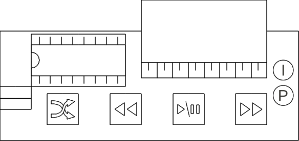
The buttons are as follows, from left to right :
 Shuffle if playing, toggle shuffled playback, else skip to random
 Skip Back skips to the previous light patch
 Play/Pause toggles automatic advancing through patches
 Skip Forward advances to the next light patch
When first turned on, the goggles are paused at the first patch.
- Press play/pause once to begin the light sequence.
- Press forward and back to move through the light patches when paused or playing.
- Press shuffle to skip to a random patch when paused, or press shuffle when playing to toggle whether or not patches are played in a random order.
The LEDs indicate :
(I) indicator LED on if playing, flashing if playing+shuffle
(P) power LED on if powered on.
When the goggles are paused, the indicator light will be off. When the goggles are playing, the indicator light will be on. When the goggles are playing back in a random order, the indicator light will be flashing.
The light program loops around to the beginning once it has reached the end. There are 123 patches.
When the batteries begin to die, the goggles should appear pink or red when first turned on, rather than white or blueish-white. The goggles will continue to operate with low batteries, although the colors will change slightly. When the batteries get low enough, you may experience unpredictable behavior, such as random restarts. There goggles are not damaged from running with low batteries, but you should replace dying batteries
Project Stages:
- The Visor
- Phase I : The Board
- Phase II : The Optics
- Phase III : Holes
- Phase IV : Power
- Phase V : Light
- Phase VI : Finish and Play
- Usage Notes